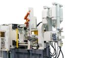
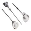
Position sensor in a cold-chamber die casting machine
How to monitor the main process variables in a cold chamber die casting machine, ensuring the highest safety standards
In a cold chamber die casting process is important:
- the real-time control with excellent resolution
- the repeatability of different process variables, such as the positions of the mold and the ejectors of the part, is important.
Thanks to our sensor, it is possible to measure in real time:
- the resistance to shocks and stresses and the control of the forces impressed at each cycle require a continuous balancing
The magnetostrictive position sensor WPP-A Hyperwave, pressure sensors KS, strain and force sensors TPSA and QE 1008 W and ML 1018 allow to get control of: the mold plate, the oil pressure of the hydraulic circuit, the nitrogen injection and the clamping force of the die.
Overview
- Application: Complete solution for monitoring the main process variables in a cold-chamber die casting machine with the highest safety standards
- Products: WPP-A Magnetostrictive transducer, KS and TPSA pressure transducers, QE1008-W and ML1018 strain transducers, TC6 thermocouple
- Results: Comprehensive portfolio of position, pressure, force and temperature transducers of Gefran enabled effective and complete monitoring of the cold-chamber die casting process
The process
In a cold-chamber die casting process, the metal is initially melted in a separate furnace.
A precise amount of molten metal is then transferred to the die casting machine where it is ladled into a cold shot chamber; the metal is finally injected into the die by means of a ram driven by a compressed gas like nitrogen. Usually the cold-chamber process is employed for metals which have a high melting point (e.g. aluminium @ 660-700°C). When the workpiece is cold, the die cavity opens and the ejector pins make it fall out.
The challenge
- This application requires a real-time control with excellent resolution and repeatability of several process variables such as the mould and workpiece ejector positions.
- The very fast injection system, stressing all the mechanical components of the machine requires high resistance to shocks and vibrations.
- Moreover, the forces impressed on the four columns supporting the moving die half (to avoid burrs in the die-cast part) must be balanced and constantly monitored at each cycle.
- Fractures in the mould or columns can raise serious safety concerns in addition to economic damage.
Product benefits
Hyperwave WPP Position Transducer
- The WPP-A Magnetostrictive transducers with a position sampling frequency of 2 kHz, equals to a reading update every 500 𝜇 This offers real-time position control of the main mechanical movements
- High resolution up to 0.5 𝜇m
- Position repeatability of 0.1 mm
- Resist shocks up to 100 g, vibrations up to 15 g
KS Pressure Transducer
SIL2 certification ensures high level of safety standards
TPSA Pressure Transducer
Innovative mechanical structure makes it insensitive towards tightening – most suitable for applications calling for robust structure and high accuracy.
QE 1008-W and ML1018 Strain Sensors
- Simultaneous strain measurement of four tie bars
- Direct display of strain value
- Wireless transmission
- Easy, fast and non-destructive mounting
Solution
Movable die half and ejector pins position control:
WPP-A Magnetostrictive position transducers – 2 Nos
- Transducer stroke: 1500 and 150 mm respectively, aluminium profile
- Cursor: Floating PCUR210
- Repeatability: 0,01 mm
- Signal linearity (error): ≤ ±0,02% FS
- Shock Resistance: 100 g
- Vibrations Resistance: 15 g
Oil pressure of the hydraulic circuit (250 bar):
KS pressure transducer – 1 No
Nitrogen injection pressure (1000 bar in 3-6 ms):
TPSA pressure transducer – 1 No
Mould clamping force adjustment:
QE1008-W strain sensor with wireless transmission– 8 Nos
Control of the forces applied to the four mould closing columns:
ML1018 strain sensors – 4 Nos
Hydraulic circuit temperature control:
TC6 thermocouple – 1 No


